
Here i’ll try to explain how to get started with Ctrlr.
What’s what, how Ctrlr is built
I’ll be using Ctrlr in Standalone mode. What does it mean ? Well if you downloaded Ctrlr there are 2 ways you can run it.
– Standalone, this means you start Ctrlr as any other program in your Operating System (this will be a “.app” on the Mac, a “.exe” on Window and a plain binary on Linux – no extension)
– As a plugin, this means Ctrlr will be loaded as a VST or a AU plugin in your favorite plugin host.
We choose the standalone mode for this tutorial cause we’ll be trying to create something new, the standalone mode gives us more freedom and has less “gotchas” that the Plugin version has. This does not mean you can’t follow this tutorial in the Plugin mode, in reality both versions of Ctrlr share exactly the same code, they’re just run differently, it’s the same code but in a different sandbox.
Let’s start Ctrlr now, after the first start you get an empty window like this:
t
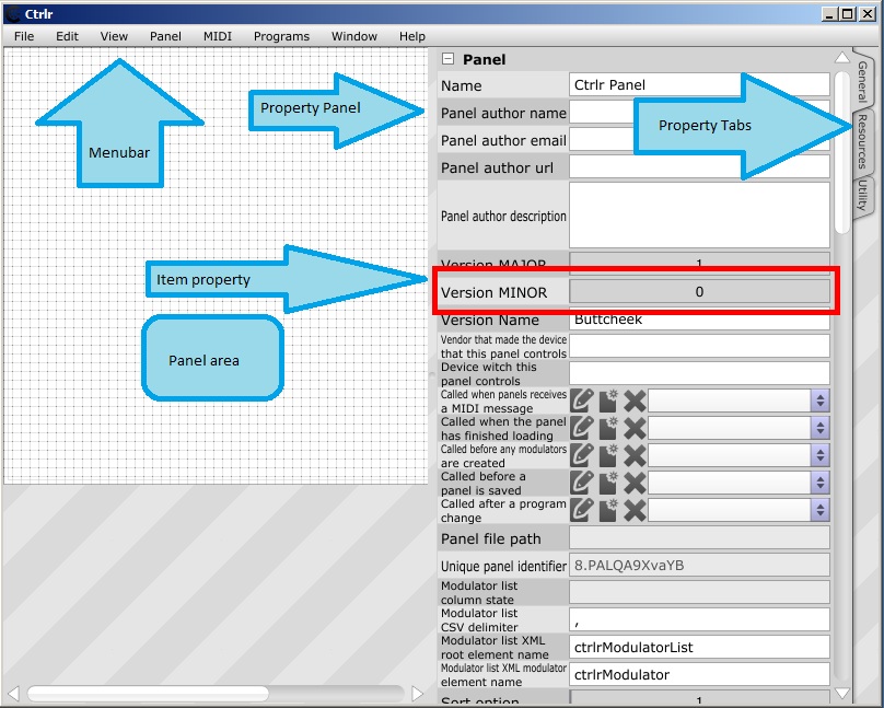
It isn’t much, first step we’ll do is choose File->New Panel and go on from there, once you do that, a more interesting view presents itself (i overlaid some blue arrows to better explain all parts):

I’ll explain all the elements of the window in detail:
- Menu Bar – this hold all the actions you can perform, some of them may be greyed out if no panel is loaded or the options is locked for some reason. IMPORTANT – if all options are “greyed out” and you can’t choose any action from the menu bar, your Ctrlr window has lost focus. This happens very often when Ctrlr is loaded as a plugin, it’s caused by how your plugin host handles plugin windows, you might need to click around the Ctrlr window to grab the focus. On some OSes in some hosts it’s almost impossible to grab the focus for a plugin window, if you find yourself in that situation, let us know of the forums.
- Property panel – this resizable pane hold the properties of whatever is currently selected, if nothing is selected the properties of the panel are displayed. The list can be scrolled and resized, there is an option to move the pane to the left side of the window if you like. The panel disappears when you exit the “Edit Mode”
- Item property – this is a singular property of whatever is selected. Different property types have different graphical representations so editing is easier. The description of the property is always in English, all the properties have a unique identifier that is well formed and is reflected as a XML property, you can view those unique identifiers by going to the “Menu Bar”, View->Property IDs/Names and refreshing the view View->Refresh property lists. Most of the time you won’t need to know the identifiers but if you get deeper into Ctrlr and start using Lua, you will need to know this, so this option might be helpful.
- Property tabs – here you will find additional utilities that relate to editing a panel. For now there are 3 tabs:
- General – the default tab for editing properties
- Resources – a resource editor where you can add/remove resources for you panels, a resource can be any file. Depending on the type of the file you will be able to use it in special ways in Ctrlr later on, most of the times you will want to add custom graphics to make your work look pretty. But any file can be a resource, later you can use that in your Lua scripts
- Utility – this realy should be named differently but was left like that for historical reasons, for now this just shows the XML of whatever is selected. Everything in Ctrlr is a XML element.
- Panel area – this is your drawing canvas, a place where you will put elements that make up your panel: Slider, Lists, Buttons, Images, Tabs, Groups etc. You place them here, then you can resize, move, selecte/de-select them.
Intel gathering phase
We’ll be making a simple panel to control a synthesizer. For this tutorial we’ll use the Dave Smith Instruments Evolver Desktop synthesizer. This is a great monophonic hybrid synthesizer from Dave Smith. I chose this unit because it uses System Exclusive messages for realtime control of it’s parameters, this is a more complicated way of controlling, but if you learn that you’ll be able to create panels for a lot more hardware, especially those older synthesizers from the 80s and early 90s (all the Yamah DX series, Roland’s Juno series and loads of others).
First thing to do is to get the MIDI specification for your hardware, without that you won’t get anywhere. Get the manual read it, try to understand it. A lot of older hardware has some very bad documentation, some of them are poorly scanned PDFs, but even if you get a nice and well formatted document, the content is bad. There is no standard here, each company had it’s own idea on how to implement MIDI, what’s even worse is the idea changed from device to device. Any hardware that let’s you dump it’s memory contents either as programs or as any custom data (for example waveforms) uses System Exclusive messages to do that. So before you go on, read about what that exactly is, the best place to start is “The MIDI Specification”, Very often those manuals will talk about Bits and Bytes, more often about “Least Significant” and “Most Significant” parts of a byte, about splitting bytes, about checksums, about encoding ASCII characters and other weird ass computer stuff you might not know. Learn this stuff if you want to continue, if you have some basic knowledge of how computers work what’s a byte and how many bits there are it should be very easy, but if you never heard of all that stuff, reading about it first will help you a lot. It might be boring and it’s mostly maths but it will allow you to understand the manual and implement it. On the bottom of this page you’ll find some more links, use them, please.
Sometimes there are some custom editors built for synthesizers, most of the time you’ll want your panel because the available editor are old, crash, not run at all, or run only on Win 3.11 or worse on Atari. But even this old software can help you, if you can get it to run. Run it in an emulated environment or a VM, use a Virtual MIDI cable. Do anything that will let you catch the MIDI data flowing between this old program and your hardware. You’ll be able to compare your findings with what the program has implemented. Look at the bottom of the page for some interesting links on this subject.
Once we got the manual, we understood it, we can get to work.
Design phase
I recommend starting with a layout. Maybe draw it on a piece of paper or in “Paint”. The idea is not to copy the layout of your synthesizer on the computer screen, why would you? Ctrlr was crated to get access to parameters hidden under layers of menus displayed on small 2×20 LCDs with no backlight, often operated using plastic membrane buttons. So try to make your layout efficient, so you get access to all parameters quickly, if there is too much stuff (some of the hardware out there has over a 100 or even over 1000 parameters), plan to put some of the stuff inside Tabs or on “Layers” that you will later make visible to the user. Group the parameters in some clever way “Oscillator 1”, “Filter”, “Filter Envelope”. Spend time to name your parameters, but keep in mind the plugin hosts that will later host your panel might “cut” your names, so try to keep them as short as possible and as descriptive as possible (i know it’s hard). I try to make names appear as paths to a parameter, for example:
the Evolver has sections of parameters: “Synthesizer”, “Global”, “Sequencer”, all my parameters will have a prefix to the section, then they’ll reflect the subsection and then name of the parameter itself. Since i try to keep those names below 8 characters (this is a limitation of the VST specification, most of VST hosts don’t really respect that limit but some do, so you decide on witch team you want to be). For “Cutoff” that is in subsection “Filter” that’s in the section “Synthesizer” i’d do, “srFltCut”, for step 1 of sequencer 1 (there are 4) i’d do “sq1Step1” etc.
It’s up to you, but remember that others might want to use it, and that memories fade and you will forget what you meant in 2 years. IMPORTANT this is your panel do whatever you want, as long as it suits your needs, all those suggestions here are very subjective.
Once you get the layout, there is one important thing to consider, will you need some custom logic in your panel. AS i mentioned above any information exchange with the device thats called “memory dump”,”sysex dump”,”bulk dump”,”program dump” involves using System Exclusive messages and custom ways of processing it. One thing that the MIDI specification does not specify is how this exchange should happen. That left a giant hole of possibilities to vendors. There is no single program that can implement all those ways. Programs like “Sound Diver” or “Sound Quest MIDI” actualy have big (in terms of amount not disk space they use) databases of additional modules, addons, plugins and scripts that do all that (if you buy the Sound Quest program you actualy get access to it via a FTP server), this is the power of those programs someone already implemented this logic for you. if you want your panel ti implement all the features your MIDI device has, and one of those features is stroing programs on your computer, you will have to at some point write a piece of Lua code to handle this. I mention this here because it might be hard for people who never wrote a single line of code to start writing code. What i can say is that i tried to make this as simple as possible, understanding your device and having the basics of computer theory will help. You don’t need to be a programmer to write this. Lua is a simple language, it’s called a “scripting” language because you don’t need a special “compiler” “debugger” “IDE” or any of that nonsense, all you need is the Ctrlr binary and some patience. So just remember if you want program dumps, Ctrlr will need your assistance in form of a script.
Getting started.
Let’s start the actual work. First we’ll create the “Oscillator” sub section section of the “Synthesizer” section. When we look at the manual we get a list of parameters for oscillators (in the Evolver manual this is the program parameter data), the parameters are:
- Oscillator Frequency [Common], Range 0-120
- Oscillator Fine Tune [Common], Range 0-100 (-50 – 0 – 50)
- Oscillator Shape [Common], Range 0-102 but 0-2 different then 3-102, for OSC3 and OSC4 range 0-127
- Oscillator Level [Common], Range o-100
- Glide [OSC3 and OSC4], Range 0-200 with sub ranges inside
- FM [OSC3 and OSC4], Range 0-1 a Boolean value
- Ring Mod [OSC3 and OSC4], Range 0-1 a Boolean value
- Shape Mod [OSC3 and OSC4], Range 0-4
This list helps us see how we should place our components. When we look at the value range for each of the parameters we should decide what UI element will be best suited for this parameter. Large linear values are good for Sliders (oscillator frequency, oscillator level, fine tune). Things that longer descriptions and have just a few values are good for Combos or ListBoxes (oscillator shape). All boolean (true/false) values are best suited for ToggleButtons.
Let’s create the oscillator 1 controls (components), for now we’ll just place the on the Panel area. Right click on the panel area somewhere, select and “Sliders”->”uiSlider”, a new rotary knob will appear on the Panel area, drag it around, resize it do what you like with it.

You will also notice that when you select that slider the set of properties to edit on the Property panel changes, you will see a set of properties that apply to the slider itself, for now scroll down the Property panel and change some colors for this new slider, you will get the basic idea of how the Property panel works. For the Oscillator 1 let’s create 4 sliders and one Combo (uiCombo can be found under Buttons in the menu). Here is the relevant properties we want to set to those new components:
Slider->Oscillator Frequency
- Name – srOsc1Freq
- Visible name – Frequency
- Minimum value – 0
- Maximum value – 120
- MIDI message type – SysEx
- SysEx Formula – F0 01 20 01 01 00 ms ls F7
Slider->Oscillator Fine Tune
- Name – srOsc1Fine
- Visible name – Fine Tune
- Minimum value – -50
- Maximum value – 50
- MIDI message type – SysEx
- SysEx Formula – F0 01 20 01 01 01 ms ls F7
Slider->PW
- Name – srOsc1Freq
- Visible name – Frequency
- Minimum value – 0
- Maximum value – 99
- MIDI message type – SysEx
- SysEx Formula – F0 01 20 01 01 02 ms ls F7
Slider->Level
- Name – srOsc1Freq
- Visible name – Frequency
- Minimum value – 0
- Maximum value – 100
- MIDI message type – SysEx
- SysEx Formula – F0 01 20 01 01 03 ms ls F7
Combo->Shape
- Name – srOsc1Shape
- Visible name – Shape
- Combo contents [seperate entries with new lines] – Sawtooth, Triangle, Sawtooth/Triangle Mix
- MIDI message type – SysEx
- SysEx Formula – F0 01 20 01 01 02 ms ls F7
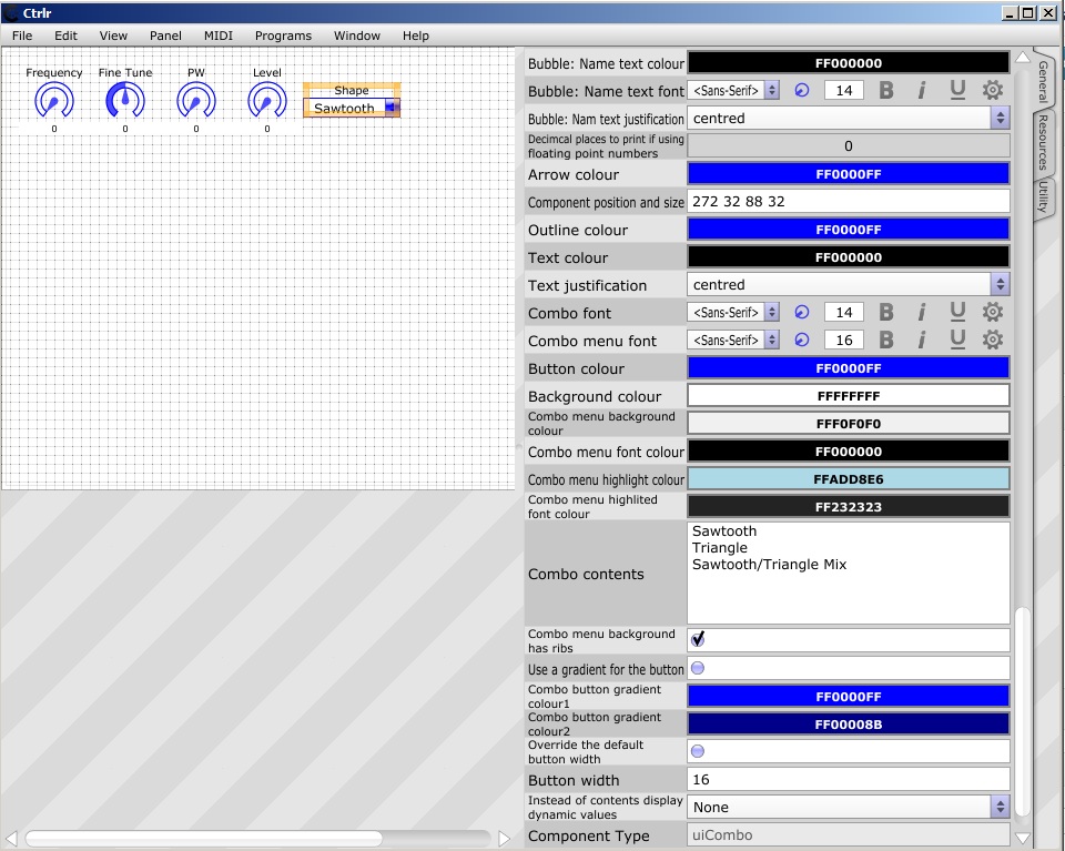
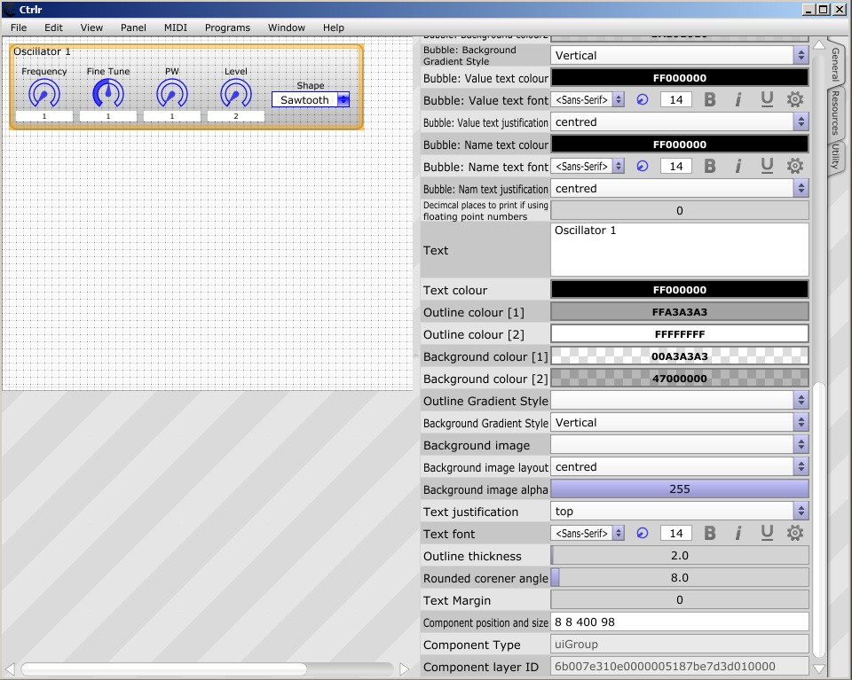
We’ll get back to the MIDI stuff a bit later, for now let’s focus on getting our sliders in place and where we want them. Let’s try to group our components, create a new uiGroup component “Groups and views”->uiGroup. Resize it so it can fit all our Oscillator components, give it some useful properties like the Text, the background colors etc. Once there, drag each of the Oscillator components onto the uiGroup, you will notice that the dragged component will “jump into” the group component, it will become a “child” component of the group, now moving the group will move all it’s children, you will also get an option to copy the group and it’s contents and later paste it anywhere on the Panel.
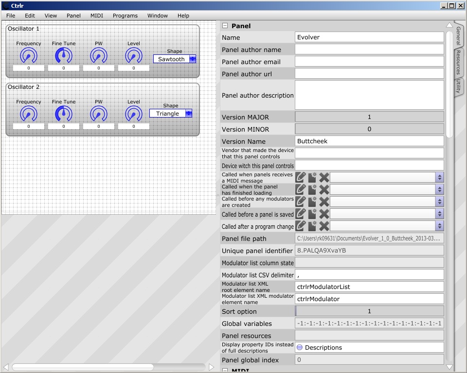
Let’s do that now, we have 4 oscillators but they share properties in pairs (oscillators 1 and 2 are analog while 3 and 4 are digital). So let’s right click on the group and select “Copy with children”, it does exactly that, it copies the group component and it’t contents. Now let’s pick a position somewhere below the already existing group, right click and “Paste”. Now we have a copy of the first Oscillator group. Select one of the components in the new group (the one below), notice how the modulator names have changed, they had to, those names should be unique within a panel, Ctrlr will just add numbers to the end of the name. Rename your components to match the Oscillator to controls, keep in mind that the System Exclusive formulas must also change since the Oscillator 2 controls have different parameter numbers inside Evolver. Here is a list for Oscillator 2:
Slider->Oscillator Frequency
- Name – srOsc2Freq
- Visible name – Frequency
- Minimum value – 0
- Maximum value – 120
- MIDI message type – SysEx
- SysEx Formula – F0 01 20 01 01 04 ms ls F7
Slider->Oscillator Fine Tune
- Name – srOsc2Fine
- Visible name – Fine Tune
- Minimum value – -50
- Maximum value – 50
- MIDI message type – SysEx
- SysEx Formula – F0 01 20 01 01 05 ms ls F7
Slider->PW
- Name – srOsc2Freq
- Visible name – Frequency
- Minimum value – 0
- Maximum value – 99
- MIDI message type – SysEx
- SysEx Formula – F0 01 20 01 01 06 ms ls F7
Slider->Level
- Name – srOsc1Freq
- Visible name – Frequency
- Minimum value – 0
- Maximum value – 100
- MIDI message type – SysEx
- SysEx Formula – F0 01 20 01 01 07 ms ls F7
Combo->Shape
- Name – srOsc2Shape
- Visible name – Shape
- Combo contents [seperate entries with new lines] – Sawtooth, Triangle, Sawtooth/Triangle Mix
- MIDI message type – SysEx
- SysEx Formula – F0 01 20 01 01 06 ms ls F7
Let’s change the display name for the group so it looks nice. In the end we should be looking at something like this:
A word about static Components (modulators). Some of the elements (uiGroup, uiTabs, uiLabel, uiImage and others) you add to your panel are considered static, they have a special property set “Modulator does not react to value changes”, and have less properties in the “Modulator” section, also no MIDI section at all. Those components are used only for displaying stuff on the screen, they help to organize your editor. Name those components in a more “human” way, since they won’t be visible to Plugin Hosts, those names can be very long and more descriptive.
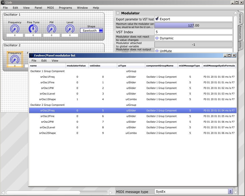
We have some components on the screen, we can see them place them, but what if we want to verify one of the property for all the components. For example we quickly want to see all the System Exclusive formulas for all components on our panel. We can do that by clicking each one sure, but it will take time. There is a utility view for a panel called “Modulator List”, you can view it from the MenuBar->Panel menu, do that now. A window with lots of columns should appear, you can adjust what columns you want to see in the Modulator List’s Menu Bar, under View->Visible columns. Columns are named after raw IDs we talked about earlier, this will help with sorting columns and takes less space on the screen. Please notice that when you select a modulator/component on the list, the same selection is reflected on the panel, this might be helpful if you mi-placed your component, it went off the screen or is hiding under some other component, you can use that list to locate those “lost” components.
Okay so we have our 2 analog oscillators in place, let’s jump to the 2 digital oscillators, the controls will be slightly different but similar. We can copy one of the already existing groups and adjust it to fit the new digital oscillator, or we can create it from scratch. I chose to create it from scratch to give it a different look. What’s different here ? First of all the shape is a linear value of 0-128 so no need for a combo, just a slider. But we have 3 new parameters that are specific to digital oscillators, here is how we’ll create them: FM – Toggle Button, Ring Mod – Toggle Button, Shape Mod – Combo.
But wait we missed one parameter for each oscillator, the Glide parameter and there are two oscillator specific options for the analog oscillators, the Sync and Slop parameters. Sync is between oscillators 1 and 2 the Slop is a global parameter, all 4 oscillators have a Glide control, we need to add that to the analog ones and include that in the digital oscillators. This is a good place to think about the layout, since the Sync and Slop parameters are only linked to Oscillators but do not affect any single one of them, we need to make sure we can see that on the panel.
For grouping the oscillators together we’ll use a parent group for those Oscillator groups, things to remember when working with groups:
- Name the group before adding any components to it, if you rename your group while some components are inside it, you need to change the property “componentGroupName” to match your new name
- Putting groups inside other groups is possible, but be aware that it’s buggy, some mouse events might occur that will place your components off screen or make them invisible etc. If something like that happens always refer to the “Modulator list”, you can there change your components coordinates manualy by editing the “componentRectangle” property
After some work, re-colouring, resizing, re-positioning, assigning names, grouping, setting SysEx formulas, this is what you should have more or less, choose your colors choose your shapes and your placements, you should have the same MIDI SysEx formulas set though (that’s written in the manual):
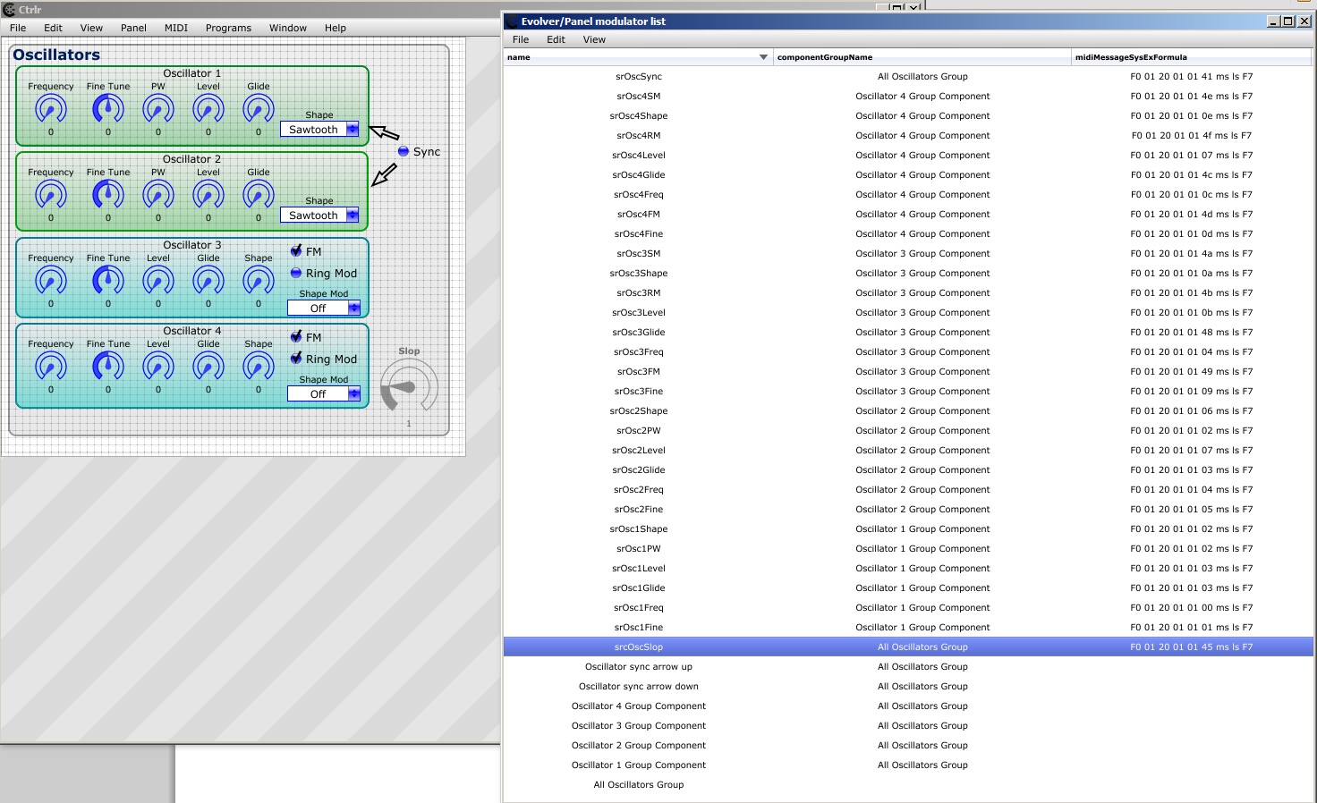
If you want to verify your data, ctrlr_tutorial_modulator_list_1, so you can copy/paste stuff (you can always do that in the Modulator List window).
IMPORTANT, when changing SysEx formulas using the Modulator List or the normal Property panel, remember to set the type first, set it to SysEx then type in the formulas.
HINT, you can multi select components on the panel using the CTRL+click combination, the Property panel will display all common properties for the selected components, their MIDI and modulator properties (the properties they share, any property that does not belong to ALL selected components will not be shown), you can then change any property in bulk.
At this point we’ll end the editing part of the tutorial, now you know how to add stuff to the panel, how to edit it, how to group it. Experiment with other components, see how they work, change them. The idea is always the same.
What’s all that MIDI SysEx formula about?
We need to dig a bit deeper into that MIDI stuff we used in the panel but didn’t payed a lot of attention to. I’ll try to explain this on an example, we’ll use the Glide parameter for Oscillator 1 for this. First let’s look at the manual what it says about this parameter, go to page 47 of the PDF manual, to the section called “Sysex Exclusive Messages”
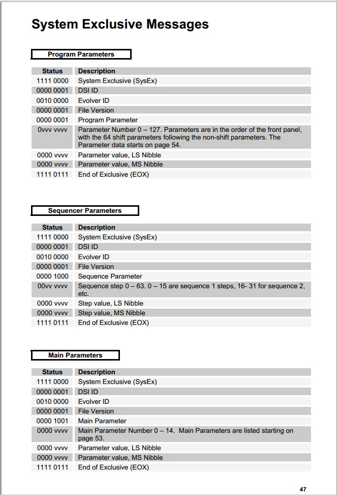
Let’s have a closer look at the table titled: “Program Parameters”, it’s a nice table, trust me. Most of the time the manufacturers of MIDI hardware are not that nice and their description of System Exclusive Data is bad or worse then bad, sometimes it’s not even there at all. Sometimes the description will be very good but so complex you simply won’t get it the first time (i think the most over complicated SysEx implementation that had to be written by someone on some serious drugs is the Casio CZ series MIDI implementation). But back to our table, we get this set of Bits called “Status” and a Description, we need to translate this to a SysEx Formula that fits into Ctrlr. How to do this ? First of all we need to convert those bits into Hexadecimal values, this will make things a bit more readable, you can use any calculator for this, but Ctrlr has one built in, just go to “Window->MIDI Calculator“, and one will appear. Now type in those bits from the table in to the “Binary” input, exactly as their written, replace any “v” or “x” or “y” or anything that’s not “0-9” and “A-F” with zeros, change the combo in the calculator to: “HEX String format“.
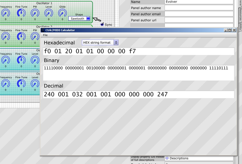
Now our bits appear a bit closer to what we used in our “SysEx formula” property before. Though not exactly the same we can try to decode it now, the data in Hexadecimal we got is:
f0 01 20 01 01 00 00 00 f7
Ok let’s start at the beginning. This magic string is a representation of a piece of computer memory, 9 bytes each byte being represented by a set of 8 bits we typed in from the manual (zeros and ones). The representation is written in base 16 notation also known as HEXADECIMAL.If you don’t understand what’s all this about read about it, you need to know this math stuff to get further and if you want to understand what’s happening. I’ll assume you know the difference between base 16 (hexadecimal), base 10 (decimal), base 2 (binary) notations, i’ll also assume you can use a calculator to convert between those types (when in doubt use the Windows calculator in “Programmer” mode). What is important here and is different then your usual 8bit per byte mumbo jumbo, is that MIDI uses only 7bits per byte, that’s how someone designed it in the eighties (that someone waas Dave Smith). So one MIDI byte is 7bits, one computer byte is 8bits. What does it mean for us ? We’ll we get one big limitation in MIDI we can’t send more then 128 values in one byte, if we used all 8bits we could send 256 values, but since we got only 7 that’s 2^7 and that’s 128. Google this a bit more if you are unsure what this means, i don’t know if writing more will explain it better, use a calculator try to convert some values, try below 127 and above see what you get from that.
Let’s go through our data from the MIDI Calculator byte by byte
- F0 – this tells us a lot, it’s a start of a Sysex Exclusive Message that’s defined in the MIDI Specification, all SysEx (SysEx is short for System Exclusive) messages start with this byte, it never changes.
- 01 – in the table from the manual, the description says DSI ID, if you look at the MIDI specification this byte is assigned to the manufacturer, each manufacturer of MIDI hardware get’s hist own byte, DSI gets 01 (it actually was Sequential Circuits), i assume they got 01 because they developed MIDI, other manufacturers get their own numbers. Beyond this byte anything goes, you can expect only the first to byte to contain this information.
- 20 – Evolver ID, this byte tells us that we are talking to the “Evolver” device, each DSI device get’s it’s own ID evolver got HEXADECIMAL 20
- 01 – File Version, this can mean a lot of things, in this case it’s internal to the Evolver specification, it’s always 1
- 01 – Program parameter, this is a more interesting byte, it tells us and the device witch section of the device we are addressing, 01 means “Program” we call that the synthesizer section
- 00 – in the “Status” column we got “0vvv vvvv” those “v” are used so you don’t confuse them with HEXADECIMAL (in hex you get only 0,1,2,3,4,5,6,7,8,9,a,b,c,d,e,f), and it specifies where we put our “bits” in, we got zero because i told you to replace all occurances of those letters with 0, that’s ok. The description column says it’s the “Parameter Number” and that the range is 0-127, so this tells us and the device witch parameter we are adressing, later this number is represented in the “Parameter list” table on page 54 of the manual
- 00 – in the “Status” column we got “0000 vvvv“, we got those “V” again, the description says it’s “Parameter value, LS Nibble”, this is where the fun starts. As i mentioned before, MIDI uses 7bits to represent a byte, that’s 128 values (0-127 or any other numeric range that has 128 values). What if we want to send,receive larger values ? This is when we split our large values into smaller ones. Instead of writing the details here i’ll write it down in a dedicated chapter, go to it now if you don’t know what LS nibble means, if you know what we are talking about, then just continue
- 00 – in the “Status” column we got “0000 vvvv“, “Parameter value, MS Nibble”, look at the byte above for more info
- F7 – this tells us that it’s the end of a SysEx message, this is also defined in the MIDI specification and a System Exclusive message always ends with F7
Splitting hair and bytes in MIDI
Here we’ll discuss how big numbers are sent using MIDI messages. First of all there are many ways to do that, i’ll describe the most common two i know of. Knowing the MIDI world there are others, if you find them you’re on your own i’m afraid, all i can do is help you on the forums.
One way of sending large numbers in MIDI that’s well documented and considered a standard is the method used for RPN and NRPN messages. Those messages can carry a number in the range of 0-16364, that’s 14bits of data, in two 7bit bytes, sent in two separate messages. The idea is simple really, there is a lot of maths involved, but in essence you take your number, represent it as 14bits take the first 7 send it, take the other 7 and send it. Those 7bit parts of a 14bit number are called “Least significant bits” for the first 7 bits, and “Most significant bits” for the second part, remember that we read bits right to left. So we start with Least and go to Most significant parts, this is the same with bits in a byte, the lowest bit (rightmost) it the least significant, the highest is the most significant.
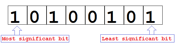 For bits in a byte
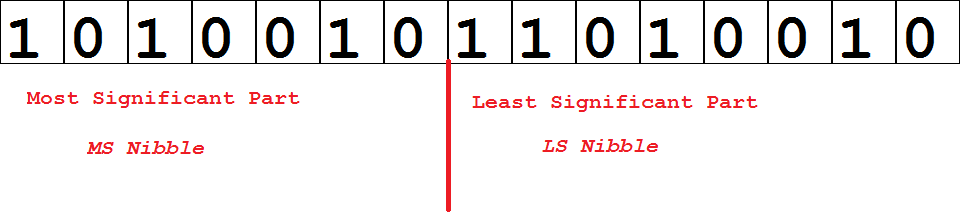 For splitting a 14bit messages into 7bit parts.
So this is the most common way, take a 14bit value split it in two 7bit values and send it in two messages, in case of NRPN and RPN the messages used are Continues Controller messages aka CC. It needs to be said that not only the value is 14bits but the controller number is 14bits, so in order to send a value change for one NRPN or RPN parameter you need to generate 4 CC messages (it’s all explained in the MIDI Specification under RPN messages).
Sometimes there is no need for 14bits, sometimes 8bits is enough (that’s 256 values), so instead of splitting a 14bit value we split a 8bit value, now we can use the same maths and rules as for NRPN and RPN messages, and that would be fine. Sometimes though, the split happens at 4bits, that’s an 8bit message split into two 4bit values, this works too but it generates a different set of values. This 4bit split is used in the Evolver Desktop synthesizer.
 Evolver specific LS/MS split.
These are the two most commonly used methods of encoding large numbers into MIDI messages, there are others i imagine, but so far those two were enough.
Now knowing this, we look inside Ctrlr, the property “SysEx formula looks like this”:
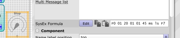
Two things about that property.
- The text field is just a quick preview of the formula, you can edit this in here but it’s not the only way
- The “Edit” button opens a special formula editor, and right clicking on a byte opens a Menu for inserting special “tokens”

I’ll explain all the menu entries here:
Insert vriable:
- MIDI Channel (7bits), insert the current MIDI output channel set for the panel in this byte
- MIDI Channel (4bits), insert the current MIDI output channel set for the panel, use the 4 least significant bits for the channel number, you can alter the most significant 4 bits by setting a HEX digit
- LSB part of value (7bits), insert the 7 least significant bits of the modulator value into this byte
- MSB part of value (7bits), insert the 7 most significant bits of the modulator value into this byte
- LSB part of value (4bits), insert the 4 least significant bits of the modulator value into this byte
- MSB part of value (4bits), insert the 4 most significant bits of the modulator value into this byte
- Insert the “upper” byte of the JV1010 encoding method, this is a special Roland method of sending larger numbers used in the JV synth series
- Insert the “upper middle” byte of the JV1010 encoding method, this is a special Roland method of sending larger numbers used in the JV synth series
- Insert the “lowe middle” byte of the JV1010 encoding method, this is a special Roland method of sending larger numbers used in the JV synth series
- Insert the “lower” byte of the JV1010 encoding method, this is a special Roland method of sending larger numbers used in the JV synth series
Insert static:
- SysEx start just inserts F0, the start byte of any SysEx message
- SysEx EOM, insert F7 the END OF MESSAGE byte of any SysEx message
- Venod ID (sub menu), inserts the Vendor Id as defined by the MIDI standard (it’s an old list, but then again the list is not updated that often)
Checksums tN t=type N=num bytes to count
All checksums have the same format, tN, where the “t” token indicates the type of checksum to calculate, and N is a number that tells Ctrlr how many bytes to before the checksum byte to include in the checksum algorithm (a checksum is a number that verifies if the reception of data is correct, it needs some data to be calculated, so the N number tells Ctrlr how much data to read)
- Roland JP8080 checksum, (zN for example z5)
- Waldorf Rack Attack checksum (wN for example w5)
- Ignore this byte on input, this is a special IGNORE token, that tells Ctrlr not to use this byte when comparing incoming MIDI data, it will considered always a “match”
Global Variable
- Global variable [k0] – [kf], insert the value of global variable numbered 0-15/0-F in this byte. Global variables are a special utility used in Ctrlr. You can set their values using expressions, by linking modulators to them, or using Lua. The value of a Global Variable is saved with the panel, it’s a placeholder for numbers that can be shared across modulators without going to Lua for help.
So now we know how to handle our bytes and how to do that in Ctrlr, so our formula
f0 01 20 01 01 00 00 00 f7
Can now be set with understanding, we need to replace the “Parameter value” part of the message with a DSI specific 4bit split, since in Ctrlr we use “ls” and “ms” as tokens for that split, we write our formula for the first paramter from the manual as:
f0 01 20 01 01 00 ls ms f7
This is what we did when adding our sliders to the panel.
Now we know how and why. Armed with that knowledge we can continue adding new controls to our panel. We know how to set the formulas for all of them, choosing the right graphical representation is a matter of taste and choice. Pick your own ones, and continue with your panel. There is one thing that we still need to know, nowhere in what we already found out was there a negative number like -20, and as we can see in the manual (for that any almost any other MIDI device), there are parameters that have negative values (like panning or tuning), or at least the description of the parameter indicates that this parameter is represented by a range of values bot positive and negative (that does not change the amount of values we need to send via MIDI, -63 – 63 is the same amount of values as 0 – 127, it’s always 128 values we need to send, remember that). Let’s talk some more about negative values.
Why so negative? Sending negative values using MIDI messages
Links
MIDI Specification and other interesting MIDI documents – described but “jglatt”
MIDI Specification – the official document
Binary Hexadecimal tutorial (1) – might help you understand all the HEX DEC BIN stuff
Binary Hexadecimal tutorial (1) – might help you understand all the HEX DEC BIN stuff (some more information on most and least significant parts)
MIDI OX the MIDI swiss army knife and MIDI Yoke the virtual MIDI cable (Window only)
Free virtual MIDI cable that works on Windows 64bit
A large list of MIDI software, a lot of editors and other useful stuff
This is great documentation, Atom. well done. Wish I had this several years ago.. now… i wonder if anyone will actually READ it 🙂
I will! 😉
I have just read this, set up a single slider, and alas CTRLR is not sending midi when I change the slider value. I shall continue!
I have discovered this Tutorial fails to mention that you must enter “Panel Mode” before MIDI will be sent. Great tutorial on RPN/NRPN! I can now continue.
excellent tutorial
I’ll be mapping away on this tonight 🙂
thanks a lot for this!!
Just read this manual. NICELY DONE, SIR!
would anyone be interested in making some of these for me, im struggling in the technology!
Is there a Manual for just using Ctrlr with an existing panel? This ‘getting started’ seems to be about making a panel. How about using a panel?
Actually I was just previously seeing all midi messages show up in the console, but now I get nothing, in Midi Monitor, console or anywhere else. How do I turn them on/off again?
It looks like in the example of a 14 bit message, the diagram shows 15 bits.
This is awesome article – thank you!
Thank you for all this information. I hope, I can get by. I plan to build an editor for the KORG R3 as the original editor might not work on 64bit-Mojave. So, yes, it’s still relevant! 😉
Is there supposed to be more tutorial after “Why so negative? Sending negative values using MIDI messages”??
The tutorial has duplicate component names and MIDI formulas. Other than that, very clear!